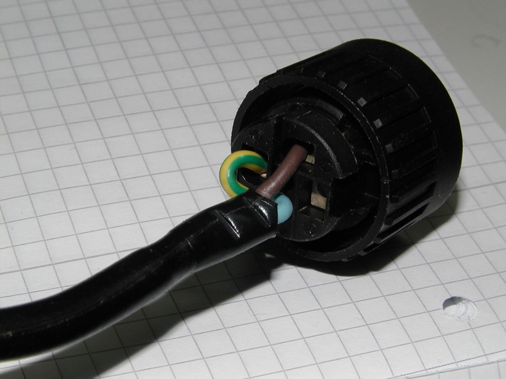
Power Connection
The Hirschmann plug used for the power connection is called Hirschmann Leitungsdose CA 4 LD 09 ZS and has the product number
932 362-100. The BS-11 includes one such plug, so unless you loose it, damage it or want multiple power cables, there is no need in obtaining this plug separately.
- GND: your shealding/earth line (PE), German:yellow/green wire
- 1: phase (L), German: Brown wire
- 2: not connected
- 3: neutral (N), German: Blue wire
Please refer to the photograph of a fully wired plug:

E1 Hardware interface
We are using a 120 Ohms balanced connection between the BS11 and a HFC-E1 card.To configure the BS11 hardware correctly, you need to
- open the connection between pin 2 and 3 of the 4 jumpers below connector J01
Cable to RJ45
The E1 interface[s] of the BS-11 are on some strange BNC-related twinax plugs called "BR2" (Radiall product # 605006000), you can find the PDF data sheet of the connectors at Radiall. There are four such plugs included in the BS-11 package. If you need more, you can buy them online from this link (which for Germany results in a hyperlink to this page of the Farnell webshop where they cost EUR 16.51 each).
- left Y01 PCM in (from BSC): RJ45 pin 4,5
- Y02 PCM out (to BSC): RJ45 pin 1,2
- Y03 PCM left open
- Y04 PCM left open
the polarity of the two wires (4,5) or (1,2) inside one twinax plug does not matter, as the signals are symmetric anyway.
Firmware / Minimal Configuration
The BS-11 runs firmware. The firmware consists of- the SMU safety load (has to be loaded over RS232)
- the actual firmware images for the individual components inside the BS-11
Firmware can be installed using either the proprietary 16-bit windows program LMT, or the bs11_config program which is part
of OpenBSC.
There is also a object database for the physical and functional objects inside the BTS. The object database consist of a set of attributes (and their values) for each object. Most parts of this database are stored in non-volatile memory of the BTS.
the so-called Minimal Configuration consists of those objects and attributes that need to be configured over the RS232 link
before an A-bis over E1 connection can be made. After the minimal configuration has been established, all other steps such as
software download and further configuration can be done over the E1 link. The minimal configuration needs a valid SMU safety load
installed.
bs11_config
Please see the bs11_config page.
The actual configuration of the objects is compiled-in. You can only change it by changing the source code.
LMT
If you're using LMT, you have to use the following procedure for firmware download and settings for the BTSM object:
- Start LMT Release 04.21(!) and make sure the cable is connected.
- Set the serial port to the port you connected your serial console
cable to - Logon as Administrator (Password is "admin")
- The factory configuration will not have any software installed
(Phase will show Software required) - Select Software->Download SM Safety Load to load BTSBMC76.SWI from
the HS010876 directory - After the download completes the BTS will restart and enter Phase
Wait Min Config - Create an Object "LI", "GPSU", "ALCO", "CCLK", "BBSIG 0", with the
default config - Create an Object "PA 0" with the following config: "GSM 0,03W(M3)"
This point is important to reduce the antenna power output! - You will need a special password to activate "BBSIG 1" and "PA 1"
Configuration is analog to Channel 0 - Create Object "EnvaBTSE 0" up to "EnvaBTSE 3" with the default
options - As soon as all configuration options are set up the BTS will enter
the Maintenance phase and you will be able to load the main firmware - Select "Download SM" in and select the file HS011106.SWL from the
HS011106 directory - Grab a coffee and occupy yourself for about 45mins
- In BTSM Object set Timeslot no. to 1, Subslot no. to 64kbit/s
signalling and TEI to 25
Updated by laforge over 8 years ago · 18 revisions

