Actions
IcE1usb » History » Revision 11
« Previous |
Revision 11/32
(diff)
| Next »
laforge, 08/22/2020 07:25 AM
iCE40 E1 USB interface
This page is the main entry point for the (completed!) "Software defined" E1 USB interface using the iCE40 FPGA at its core.
Architecture
This approach tries to implement as much as possible inside an iCE40 FPGA
Particularly, the iCE40 FPGA- contains the E1 PHY. There is no external LIU*, reducing the BOM cost significantly. Instead, the comparators of the FPGA are used. In practice, this has shown to work on short E1 links of a few meters. We'd expect some problems in terms of long-haul E1 links, but those are not really the target use case here.
- contains the E1 framer, including frame alignment, CRC4 verification/generation, ...
- contains a USB softcore (no external USB PHY needed)
- contains a PicoRISCV softcore to implement USB protocol handling and to connect the E1 softcore with the USB softcore
So all-in-all, we can build a USB-E1 interface from little more than an iCE40 FPGA and an E1 line transformer!

Current stack
- The hardware is currently not documented, only few prototypes exists and have been half hand-wired. They are currently based off iCEBreaker and iCEBreaker-bitsy iCE40 dev boards. ( https://github.com/icebreaker-fpga/icebreaker ) as well as iCEpick by tnt
- The gateware is temporarily hosted in the 'e1' branch of this repo : https://github.com/smunaut/ice40-playground/tree/e1/projects/riscv_usb
- The embedded software is in the same repository as above, in the 'fw' sub-directory : https://github.com/smunaut/ice40-playground/tree/e1/projects/riscv_usb/fw
- The userspace daemon that handles the USB communication is hosted at: https://git.osmocom.org/osmo-e1d
- The support for this daemon interface to the rest of the cellular stack is merged in mainline libosmo-abis. Make sure you build it with
--enable-e1d, though.
Presentations
- Talk from OsmoCon 2018 about the Software Defined E1 project as a whole : osmocon_2018_e1.pdf
- Talk from OsmoDevCon 2019 about the iCE40 based solution specifically: osmodevcon_2019_e1.pdf
- video recording of the iC40 based approach / OsmoDevCon 2019
Status
Hardware
- Several hand-wired pre-production prototypes based on iCEbreaker and iCEbreaker-bitsy or iCEpick have been assembled and used successfully in 2019 and early 2020
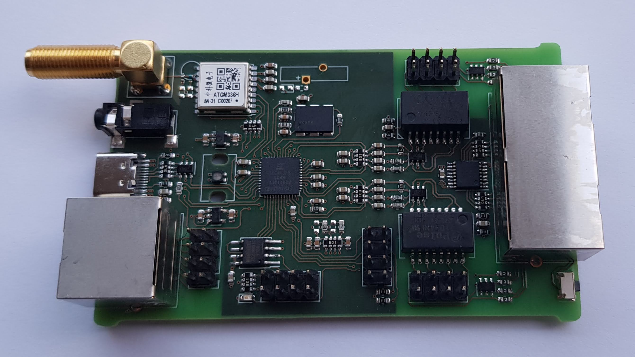
- A fully integrated single-board design with two E1 lines and a GPS-DO for E1 clock stability has been created by tnt in August 2020; prototype boards exist, and we expect a first production run is imminent.
Early Prototype
")
Pre-production Prototype
Software
The full stack from gateware through firmware and host software has been tested and used in a variety of scenarios.
- gateware for the FPGA and firmware for the RISC-V softcore is available from the
e1branch ofice40-playground.git, see https://github.com/smunaut/ice40-playground/tree/e1 - The host software/driver is part of osmo-e1d, see the proejct page for related details. libosmo-abis has been extended with osmo-e1d support.
Credits
The development of FPGA softcores, firmware, PCB schematics, PCB layout and osmo-e1d was done by Sylvain Munat (tnt).
Updated by laforge almost 4 years ago · 11 revisions

