BildTel 001 » History » Revision 20
« Previous |
Revision 20/27
(diff)
| Next »
laforge, 11/04/2023 03:40 PM
- Table of contents
- BildTel 001
BildTel 001
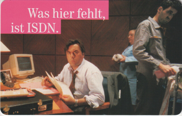
The Telekom-branded BildTel 001 was likely the first commercially available ISDN video phone in Germany.
(Only digital marketing picture I could find online, courtesy of Picture Allianze / Matthias Hiekel)
The specific unit I managed to acquire has been with the Hochschule für Telekommunikation Leipzig until its closure in 2022.
Architecture
The system consists of the following parts:- A TV screen with built-in BTX decoder (inherited from LOEWE_Multitel_TV10)
- A keyboard + phone-receiver combo (inherited from LOEWE_Multitel_TV10)
- A desktop-computer-like box called the Codec (containing the actual ISDN video telephony part, implemented by AEG/OLYMPIA)
- A video camera
The BTX Terminal LOEWE_Multitel_TV10 was used as the "user interface" for the device, adding the codec box to turn it into a video phone.
Codec unit
- 1x power supply
- 4x "mainboards" stacked on top of each other (two sandwiches of two PCBA)
- top two boards (CODER / DECODER) have a number of DIN 41612 slots for plug-in cards
- 6x CODEC ADSP boards plugged into slots of the CODER
- 3x CODEC ADSP boards plugged into slots of the DECODER
- 1x OUTDIG/OUTANA sandwich, consisting of two PCBA plugged into slots of the DECODER mainboard
- this is the TV output board, generating and digital-analog-converting analog TV signal
- 1x INDIG/INANA sandwich, consisting of two PCBA plugged into slots of the CODER mainboard
- this is the camera input board, receiving and digitizing the analog TV camera signal
AEG-OLYMPIA CODEC ADSP
This board exists 9 times in total (6x for CODER, 3x for DECODER). It hosts a digital signal processor, RAM and some FIFOs.
There are no visible differences between the boards; also the label on the GAL is identical.
PCB Marking: 1601914L11T
Connector Marking: None
| ADI ADSP-2101 | Digital Signal Processor |
| VX-8111 10.0000 MHz | Crystal Oscillator |
| GAL20V8A (4012-001/2) | GAL |
| 2x IDT 7201SA25J | FIFO |
| 2x IDT 7202SA25J | FIFO |
| 3xCY7C199-45VC | RAM |
AEG-OLYMPIA OUTDIG
PCB Marking: 2401913L1T
Connector Marking: 35.103-3030.2 SN. 3051
top PCBA:
| Brooktree Bt101 | Triple 8-bit VIDEODAC |
| Xilinx XC2018-100 | FPGA 100 CLBs, 1000 Gates |
| S-Data SXO-300C 27.00000 MHz | Crystal Oscillator |
| 3x IDT 7201SA25J | FIFO |
AEG-OLYOMPIA OUTANA
TBD
AEG-OLYMPIA INANA
This is the analog input board.
PCB Marking: 0202914L1T
Connector Marking: 35.103-3023.8/01
AEG-OLYMPIA INDIG
This is the digital input board, containing the video ADC and support circuitry
PCB Marking: 0202915L1T
Connector Marking: 35.103-3020.2/01
| Brooktree Bt253KPJ | Color Video ADC |
| Xilinx XC3030-70 | FPGA |
| DOC31CC 27.000M | Crystal Oscillator |
| 3x TI TLC272CP | OpAmp; likely buffers for analog R/G/B |
| 0900-002/2 | SPI flash for FPGA bitstream? |
| 3x QSL QS8201-15JR | 512x9 FIFO |
TV Camera
TV / BTX Unit
BTX decoder
- EPROM image: bildtel001_tv10_btxdecoder_16772_074_349_27C010.bin
Keyboard/receiver unit
Actual Cherry keyboard PCBA after full disassembly, ultrasonic cleaning of all keycaps and lots of isopropanol on the PCB, removing what might be decades old coke residue:
Connections
Codec unit
- connects to ISDN basic-rate S0 interface using 8P8C/RJ45 plug
- has two proprietary connectors for attaching video cameras
- has two SCART connectors (one for audio/video output to the TV)
- has a TAE jack for attaching an analog phone for the audio port (connected to the combined keyboard/receiver unit by default)
- has another TAE jack (purpose unknown)
- has a V.24 interface on a SUB-D 9 connector which connects to the built-in BTX decoder of the TV unit
TV Camera
- connects to the Codec unit using a proprietary high-density connector that appears to carry both video and power
TV unit
- has an RF input for TV broadcast signals (PAL)
- has a SCART input for baseband audio/video from peripherals (like the Codec unit)
- has a DIN speaker output for attaching an external speaker
- has a built-in BTX decoder with
- an unused DIN port intended to connect to the DBT-03 BTX-Modem (not used in the ISDN video application)
- an unused centronics port
- an auxiliary V.24 port on a DIN connector interfacing the SUB-D 9 of the Codec unit
Keyboard/receiver unit
- has a cable with TAE connector attached (connects to codec unit)
Further Reading
Updated by laforge 9 months ago · 20 revisions

